- 您现在的位置:买卖IC网 > Sheet目录3833 > AT87251G2D-3CSUM (Atmel)IC 8051 MCU 32K OTP 24MHZ 40DIP
50
AT/TSC8x251G2D
4135F–8051–11/06
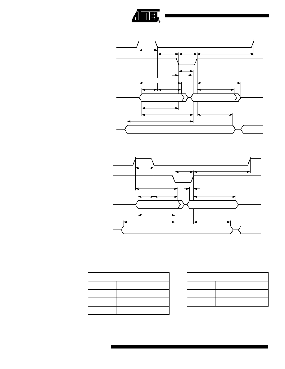
Figure 12.
External Bus Cycle: Data Read (Page Mode)
Note:
Figure 13.
External Bus Cycle: Data Write (Page Mode)
Note:
AC Characteristics - Real-Time Synchronous Wait State
Definition of Symbols
Table 41.
Real-Time Synchronous Wait Timing Symbol Definitions
TAVDV2
(1)
TAVDV1
(1)
TLLAX
TRHAX
TRHDX
TRHDZ2
TAVLL
(1)
TAVRL(1)
P0/A16/A17
P2
RD#/PSEN#
ALE
TLHLL(1)
TRLRH(1)
TLHAX
(1)
Data In
A7:0/A16/A17
TRLAZ
TLLRL(1)
TRHLH2
TRLDV(1)
D7:0
A15:8
TWHLH
TAVWL2(1)
TAVWL1(1)
TLHAX
(1)
TLLAX
TWHQX
TWHAX
P0/A16/A17
P2
WR#
ALE
TLHLL(1)
TWLWH(1)
Data Out
A7:0/A16/A17
TAVLL(1)
TQVWH
A15:8
D7:0
Signals
Conditions
C
WCLK
L
Low
R
RD#/PSEN#
V
Valid
W
WR#
X
No Longer Valid
YWAIT#
发布紧急采购,3分钟左右您将得到回复。
相关PDF资料
AT80C51RA2-SLSUM
IC 8051 MCU ROMLESS 44PLCC
AT80C51RA2-SLSUL
IC 8051 MCU ROMLESS 44PLCC
AT80C51RA2-RLTUM
IC 8051 MCU ROMLESS 44VQFP
213931-5
CONN JACKSCREW RECEPT 34 POS
AT80C51RA2-RLTUL
IC 8051 MCU ROMLESS 44VQFP
AT80C51RA2-3CSUM
IC 8051 MCU ROMLESS 40DIP
AT80C51RA2-3CSUL
IC 8051 MCU ROMLESS 40DIP
AT80C31X2-SLSUM
IC 8031 MCU ROMLESS 44PLCC
相关代理商/技术参数
AT87251G2D-RLTUL
制造商:ATMEL 制造商全称:ATMEL Corporation 功能描述:B/16-BIT MICROCONTROLLER WITH SERIAL COMMUNICATION INTERFACES
AT87251G2D-RLTUM
功能描述:8位微控制器 -MCU 251G2D 8/16bitC OTP 5V RoHS:否 制造商:Silicon Labs 核心:8051 处理器系列:C8051F39x 数据总线宽度:8 bit 最大时钟频率:50 MHz 程序存储器大小:16 KB 数据 RAM 大小:1 KB 片上 ADC:Yes 工作电源电压:1.8 V to 3.6 V 工作温度范围:- 40 C to + 105 C 封装 / 箱体:QFN-20 安装风格:SMD/SMT
AT87251G2D-SLSUL
功能描述:8位微控制器 -MCU Microcontroller
RoHS:否 制造商:Silicon Labs 核心:8051 处理器系列:C8051F39x 数据总线宽度:8 bit 最大时钟频率:50 MHz 程序存储器大小:16 KB 数据 RAM 大小:1 KB 片上 ADC:Yes 工作电源电压:1.8 V to 3.6 V 工作温度范围:- 40 C to + 105 C 封装 / 箱体:QFN-20 安装风格:SMD/SMT
AT87251G2D-SLSUM
功能描述:8位微控制器 -MCU OTP 8/16bit St 5V 24MHz RoHS:否 制造商:Silicon Labs 核心:8051 处理器系列:C8051F39x 数据总线宽度:8 bit 最大时钟频率:50 MHz 程序存储器大小:16 KB 数据 RAM 大小:1 KB 片上 ADC:Yes 工作电源电压:1.8 V to 3.6 V 工作温度范围:- 40 C to + 105 C 封装 / 箱体:QFN-20 安装风格:SMD/SMT
AT875
制造商:POSEICO 制造商全称:POSEICO 功能描述:PHASE CONTROL THYRISTOR
AT875LT
制造商:POSEICO 制造商全称:POSEICO 功能描述:PHASE CONTROL THYRISTOR
AT875LTS44
制造商:POSEICO 制造商全称:POSEICO 功能描述:PHASE CONTROL THYRISTOR
AT875S44
制造商:POSEICO 制造商全称:POSEICO 功能描述:PHASE CONTROL THYRISTOR